This is a beautiful image of Ireland taken at about 11am this morning (23 December 2010) which I grabed from the ESA's Miravi service. This image is cropped to show just the island of Ireland and is contrast enhanced. The last week or so has been a particularly severe cold snap with record low temperatures for December. The Corrib lake is seen to be partially covered by ice.
The original image is here, (12MB).
There is a similar image available from the Irish Met Office here.
Thursday, December 23, 2010
Tuesday, December 14, 2010
Arduino powered Christmas tree star
- an Arduino (and suitable power supply eg USB connection to a laptop)
- a nice powerful red-green-blue LED such as this one from Seeed Studio
- a power supply for the LED (the Arduino cannot provide the required current). I used 4 x NiMH AA cells.
- 3 x NPN transistors that saturate with Ic as close as possible to the maximum allowed current for the LED. I used 3 x BC547 as it was the only ones I had handy. Unfortunately that saturates at only 100mA (I'm allowed up to 350mA per channel for this LED), but it was sufficient for the effect to be successful.
- 3 x resistors (150 ohms or so) to limit the transistor base current which will be sourced from the Arduino PWM IO pins
- a length of 4 core cable that will run the length of your tree down to your bread board
- a breadboard (this is a very temporary hack)
A word of caution: while the voltage is low, the currents running up to the RBG LED are sufficient to pose a small (but non negligible) fire hazard should something go wrong (eg LED failure or a short circuit). Only operate this while in the room and power off while not attended.
I soldered the LED onto a square of strip board and attached it to my star Christmas tree ornament.
This particular RGB LED can sink up to 350mA per channel (1A in total). There is no way you can source this much current directly from the Arduino IO pins. Instead the Arduino switches transistors which in turn drive the LED current. The BC547 transistors I had on hand saturate at only 100mA but I found this sufficient for a reasonably good effect.
The transistor base current is provided by pins 9, 10 and 11 of the Arduino. These pins are capable of a simulated digital-to-analog conversion using pulse width modulation (PWM). A 150 ohm resistor limits the base current to about 33mA (the Arduino's limit is 40mA per pin). This is sufficient to ensure the transistor is fully on (saturated). Failure to fully saturate the transistor can lead to excessive heat dissipation in the transistor. There is no need for a LED current limiting resistor – the transistor performs that function.
The following sketch is my "supernova" program. The idea is to use this as a lighting the tree ceremony. First the star slowly comes to life in a supernova effect (with buckets of artistic licence) and when it reaches full brightness you then power up all the other traditional lighting.
Here is a video of the effect:
Here is a video of the effect:
You can easily adapt the sketch for other effects.
/*
 * Christmas tree star LED driver. Simulate "supernova" effect
 * with lots of artistic licence. You need 3 x transistors
 * to power LEDs.
 *
 *
 * See blog post:
 * http://jdesbonnet.blogspot.com/2010/12/arduino-powered-christmas-tree-star.html
 *
 * Joe Desbonnet
 * jdesbonnet@gmail.com
 * This is public domain code. No copyright is asserted.
 */

// Define pins for Red, Green and Blue LEDs.
int LEDR = 9;
int LEDG = 10;
int LEDB = 11;

void setup()  {
  // nothing to setup
}

void loop()  {
    int i;

    setRGB(0,0,0);

    // Fist a red faint red glow... growing slowly
    for (i = 0; i < 16; i++) {
        setRGB(i,0,0);
        delay(500);
    }

    // Getting brighter faster now
    for (i = 16; i < 64; i++) {
        setRGB(i,0,0);
        delay(100);
    }

    // Add some gree to make the light yellow (like dawn)
    for (i = 64; i < 200; i++) {
        setRGB(i,i-64,0);
        delay(100);
    }

    // Now a bit of blue
    for (i = 200; i < 255; i++) {
        setRGB(i,i-64,i-200);
        delay(100);
    }

    // Flash
    setRGB(255,220,128);
    delay(10);
    setRGB(0,0,0);

    delay (100);

    // Another flash
    setRGB(255,255,200);
    delay(10);
    setRGB(0,0,0);

    delay (100);


    // More flashes, with random color variations and intervals
    for (i = 0; i < 32; i++) {
      setRGB (random(192,255),
            random(192,255),
            random(192,255) );
      delay(20);
      setRGB(0,0,0);

      delay (random(50,200));
    }

   // End of program... switch LED on full all channels (~ white)
   setRGB(255,255,255);

   // Loop forever
   while (1);

}

void setRGB (int r, int g, int b) {
  analogWrite(LEDR,r);
  analogWrite(LEDG,g);
  analogWrite(LEDB,b);
}
Tuesday, November 30, 2010
Hot water tank experiment
I've been wondering why my hot water takes an unusually long time to heat up in recently. When I first moved in almost 8 years ago it seemed that it took only about 20 minutes to get piping hot water. Nowadays it takes 40 minutes or more ... and even then it's not that hot.
I was curious about the temperature profiles of my hot water tank as it was being heated by my natural gas powered water heater ("boiler" or "furnace"). As is normal in Ireland, household hot water is provided from hot water storage tank which is heated via heat exchanger by the central heating system.
The following is the temperature at the heat exchanger inlet and outlet of the hot water tank. Temperature was measured with DS18B20 temperature sensors which were taped to the pipe near the tank.
A few things struck me as being interesting about this graph. First there is a brief but noticeable dip in inlet temperature when the system is first switched on. This is clearly the cold water ahead of the pump/heater entering the heat exchanger. There is a quick rise in temperature with the outlet temperature following the input minus a temperature drop (due to heat transferred to the water in the tank) and a time lag (due to the transit time of water in the heat exchanger). However the most striking feature is the temperature cycling.
It seems that my heater cannot transfer heat to the tank fast enough. The water in the heat exchanger circuit reaches the heater's target water flow temperature (user settable from 30°C-85°C) and the flame cuts off. The pump continues to pump until the temperature drops below some threshold and the cycle repeats. The duty cycle is about 50 seconds flame on, and 180 seconds flame off.
There is another interesting effect during the cooling phase: a brief increase in temperature for about 30 seconds before dropping again. I believe this artifact is because the heater flame is on for less time that it takes for the water to circulate around the system. So there is a hot spot which makes a second round through the system.
I re-ran the experiment with a higher heater temperature:
It looked identical (excepted at elevated temperatures). But only when I looked at the numbers more closely while writing this post did I realize that the period between cycles had increased from about 230 seconds to 330 seconds. So perhaps if I set the heater at the max temperature I could increase the period to a sufficiently long time to heat the water in the tank in just one cycle.
The following graph is from a third run. This time the heater was set at the max temperature (supposedly 85°C) and I set the tank thermostat at 40°C.
Unfortunately there was still cycling, 4 in total, but the cycle period was considerable longer than any than the previous runs. More importantly the duty cycle was much better: 500 seconds of flame on, 100 seconds flame off for the first cycle; 220s on/100s off for second, 180s on / 100s off for third, and 140s on for the last cycle. The tank thermostat cut off the heater at about 1800 seconds (30 minutes) into the experiment.
Conclusion:
For fast hot water, running the heater as hot as possible works best (at least for me). At some point the heater temperature must have been turned low which explains why in recent years it seems to be taking ages for the water to heat. However all this probably makes no difference to the energy efficiency of the system.
Tuesday, November 2, 2010
Hotpoint Aquarius FDW60 dishwasher drain pump repair
A few years ago our 2004 Hotpoint dishwasher (Aquarius FDW60) started failing in mid cycle with a flashing "Eco" and "Fast" LED. The underlying cause was that the grey water drain pump wasn't pumping. There was precious little information about reparing the device on the internet. Faced with a repair bill of at least €140 we were close dumping and replacing it. I figured there was nothing to lose by investigating the problem myself and after a little puzzling over the layout of the various inards of the device I eventually located the drain pump, disconnect it, manually rotated the impeller a few times with a srewdriver, reconnected it... and sure enough everything was back to normal.
Two years later after flawless operation, the problem has returned. This time I thought I'd document the repair procedure in case it's of use to anyone else.
First a caveat: don't try this unless you are comfortable with DIY repair and have at least a basic understanding of electrical safety. The instructions here worked for me, but may not be the "correct" way of doing things. If you do decide to proceed YOU DO SO AT YOUR OWN RISK. Also, if there is any warrantee remaining on the appliance it may be voided by your attempt to repair. Feel free to add feedback below if you have any interesting information to add.
The tools you need for this are:
Empty any water remaining in the dishwasher. Remove the filters and drawers (the top drawer requires that you to remove a plastic stopper at the end of the drawer rail). Use a rag to mop up any remaining water in the drain well. Switch of the unit and remove power at the wall socket or fuse.
Before disconnecting the cold water in ensure that the water supply to the appliance is OFF. This is usually accomplished by means of a valve leaver near where the hose connects to the water supply. Leaver perpendicular to the pipe usually means OFF. Have a bucket and rag ready to catch any residual water in the hose.
Same applies to the grey water outlet hose. This water may have a foul oder -- so be prepared.
Ensure that the power cord and the two water hoses are free to move as you gently pull the appliance out.
Place some newspaper on the ground and have some rags on the ready. Stuff a rag in the drain well to absorb residual water. Gently lay the appliance on its side. Be prepared from some water to seap out. The bottom of the appliance is now exposed. Use a brush or vacuum cleaner to clean the bottom.
Double check that you have electrically disconnected the appliance (don't just rely on the appliance on/off button!). Best to physically disconnect the power cord from the wall socket. If you can't do this then trip the fuse associated with the appliance. Verify there is no power by switching the device on and ensure the power neon does not light.
The bottom panel can be removed by unscrewing 6 (Phillips Head Size 2, I think) screws marked by red arrows in photo. You may need to temporarly remove the front legs to access two of the front screws(just twist the leg until it comes out).
Most of the essential dishwasher components are now accessible. The drain pump can be removed by unscrewing one screw (see photo) and twisting the pump assembly.
The impeller should now be visible inside the pump chamber. Use a pen or screw driver to rotate the impeller a few revolutions. There will be some resistance due to the pump motor – that is normal.
Ensure that there are no foreign objects stuck in the chamber (use a torch to illuminate the chamber while rotating the impeller). In my case I found a pumpkin seed!
Reattach the pump assembly (be careful to ensure the o-ring seal is still there).
Replace the bottom panel. Bring the unit upright. Reconnect power and water hoses. Run a "Prewash" cycle to test.
That should be it!
Boot note: On my first attempt at reattaching the pump assembly I failed to engage all three posts of the bayonet twist lock mechanism (the one at the back which isn't easy seen had not engaged). This resulted in water leaking during my test which caused the float switch activate. This manifests itself as as flashing "Eco" LED and the drain pump runs continuously. Once the pump was attached properly everything ran smoothly.
Update (24 Jan 2011): I've added additional information about the this dishwasher's controller board in this blog post.
Update (7 Mar 2011): A Hotpoint technician told me that this can often be solved without removing/opening the unit by using something like a wire coat hanger to unstick the drain pump impeller. I've never tried this, so I can't comment on its effectiveness and it probably won't help if there is a foreign object lodged in there.
Update (25 May 2011): Impeller got stuck again today. This time I tried the coat hanger trick that was suggested to me by the Hotpoint technician. It worked! I had to do it twice... first time the pump started working, but it sounded rough and then jammed again. The second time it again sounded rough for a few seconds but recovered and seems to be fully back to normal now. There was probably a foreign object in the pump chamber that got expelled eventually. You need a wire coat hanger and make a right angle bend like this:
The horizontal part (running parallel to my measuring tape) goes into the drain hole. See photo of the underside of the dishwasher above to get an idea of what's going on. About 10cm - 11cm is what you need to reach the impeller. Then just wiggle it... all it takes is just the slightest movement of the impeller to unstick it. Of course if you have a large foreign object stuck in there this probably won't help – you'll need to disassemble the pump as described in the main part of this post.
Two years later after flawless operation, the problem has returned. This time I thought I'd document the repair procedure in case it's of use to anyone else.
First a caveat: don't try this unless you are comfortable with DIY repair and have at least a basic understanding of electrical safety. The instructions here worked for me, but may not be the "correct" way of doing things. If you do decide to proceed YOU DO SO AT YOUR OWN RISK. Also, if there is any warrantee remaining on the appliance it may be voided by your attempt to repair. Feel free to add feedback below if you have any interesting information to add.
The tools you need for this are:
- Phillips head screwdriver (number 2), but you might get away with a flat head
- Torch (optional)
- Bucket (optional)
- Rag (optional)
- Brush and/or vacuum cleaner (optional)
- FDW60 manual (optional)
Empty any water remaining in the dishwasher. Remove the filters and drawers (
Before disconnecting the cold water in ensure that the water supply to the appliance is OFF. This is usually accomplished by means of a valve leaver near where the hose connects to the water supply. Leaver perpendicular to the pipe usually means OFF. Have a bucket and rag ready to catch any residual water in the hose.
Same applies to the grey water outlet hose. This water may have a foul oder -- so be prepared.
Ensure that the power cord and the two water hoses are free to move as you gently pull the appliance out.
Place some newspaper on the ground and have some rags on the ready. Stuff a rag in the drain well to absorb residual water. Gently lay the appliance on its side. Be prepared from some water to seap out. The bottom of the appliance is now exposed. Use a brush or vacuum cleaner to clean the bottom.
Double check that you have electrically disconnected the appliance (don't just rely on the appliance on/off button!). Best to physically disconnect the power cord from the wall socket. If you can't do this then trip the fuse associated with the appliance. Verify there is no power by switching the device on and ensure the power neon does not light.
The bottom panel can be removed by unscrewing 6 (Phillips Head Size 2, I think) screws marked by red arrows in photo. You may need to temporarly remove the front legs to access two of the front screws(just twist the leg until it comes out).
Most of the essential dishwasher components are now accessible. The drain pump can be removed by unscrewing one screw (see photo) and twisting the pump assembly.
The impeller should now be visible inside the pump chamber. Use a pen or screw driver to rotate the impeller a few revolutions. There will be some resistance due to the pump motor – that is normal.
Ensure that there are no foreign objects stuck in the chamber (use a torch to illuminate the chamber while rotating the impeller). In my case I found a pumpkin seed!
Reattach the pump assembly (be careful to ensure the o-ring seal is still there).
Replace the bottom panel. Bring the unit upright. Reconnect power and water hoses. Run a "Prewash" cycle to test.
That should be it!
Boot note: On my first attempt at reattaching the pump assembly I failed to engage all three posts of the bayonet twist lock mechanism (the one at the back which isn't easy seen had not engaged). This resulted in water leaking during my test which caused the float switch activate. This manifests itself as as flashing "Eco" LED and the drain pump runs continuously. Once the pump was attached properly everything ran smoothly.
Update (24 Jan 2011): I've added additional information about the this dishwasher's controller board in this blog post.
Update (7 Mar 2011): A Hotpoint technician told me that this can often be solved without removing/opening the unit by using something like a wire coat hanger to unstick the drain pump impeller. I've never tried this, so I can't comment on its effectiveness and it probably won't help if there is a foreign object lodged in there.
Update (25 May 2011): Impeller got stuck again today. This time I tried the coat hanger trick that was suggested to me by the Hotpoint technician. It worked! I had to do it twice... first time the pump started working, but it sounded rough and then jammed again. The second time it again sounded rough for a few seconds but recovered and seems to be fully back to normal now. There was probably a foreign object in the pump chamber that got expelled eventually. You need a wire coat hanger and make a right angle bend like this:
The horizontal part (running parallel to my measuring tape) goes into the drain hole. See photo of the underside of the dishwasher above to get an idea of what's going on. About 10cm - 11cm is what you need to reach the impeller. Then just wiggle it... all it takes is just the slightest movement of the impeller to unstick it. Of course if you have a large foreign object stuck in there this probably won't help – you'll need to disassemble the pump as described in the main part of this post.
Thursday, October 28, 2010
Computer interface to a low cost electronic kitchen scale (part 1)
On a few occasions I was looking for a low cost electronic weigh scales with a computer interface. It seems they don't exist. There are electronic kitchen scales for as little as €15, but as soon as you require a computer interface you're into specialized scientific/point-of-sale equipment and the starting price jumps to €400+.
I had a spare low cost kitchen scale lying around that was purchased in Maplin (model KS108) a few years ago. Opening it up one can see the weight/force (also known as a "load cell") sensor is a cantilever beam anchored to the base of the unit with strain gauges glued to the top and bottom of the beam. The strain gauges are covered in a white epoxy for environmental protection. A weight (force) applied to the business end of the beam causes the beam to bend slightly causing the strain gauges on top to stretch and those on the bottom to compress.
A commonly used configuration comprises 4 strain gauges wired in a "full bridge" Wheatstone bridge. All four resistors of the bridge (see schematic further down) are strain gauges. Two on the top (R1, R4) and two on the bottom (R2, R3). This configuration provides good sensitivity to bending, and automatically compensates for resistance variation due to temperature.
The interface to the sensor comprises 4 wires: the red and black wires are are the 'excite' (labeled E+ and E- on the PCB) and white and blue are the sense wires (labeled S+ and S-).
The changes in resistance of individual strain gauges are too small to measure accurately by direct measurement. However in a Wheatstone bridge configuration the tiny changes in resistance causes the bridge to unbalance and measurable potential difference is generated on on the sense wires.
I was hoping to piggy back my own sensor electronics without interfering with the operation of the scale. Unfortunately it seems the scale's electronics was interfering with my ability to measure anything. So I cut the sensor wires and attached a simple plug / socket to allow the sensor to be connected to my system but still have the option to revert back to the original configuration if required.
After disconnecting the sensor from the scale's PCB I was able to measure a small voltage difference on the sense wires. But only 1.4mV when 1kg is applied. This is far too small to be measured directly by the ADC (each step of a 0–5V 10 bit ADC is about 5mV).
The two sense wires are connected to an op amp in differential configuration (a ST Microelectronics TS954 dual rail-to-rail op amp) set at moderately high gain produces a signal useable by an ADC.
Normally the Rg resistor is set set to the same value as Rf. In this configuration Vo is 0V when no force is applied to the sensor and can swing up the the supply rail (5V).
If Rg is omitted, at rest (zero force) the output from the op amp (Vo) is about 2.5V. Depending on how the sense wires are connected to the op amp, Vo can swing from 2.5V to 5V or from 2.5V down to 0V (the ground rail). So it seems we lose half of the ADC's dynamic range. However we can put this situation to good use.
Let's call the voltage change due to the application of force on the sensor as ΔV.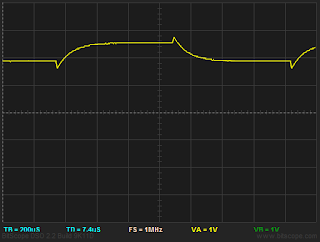 Instead of wiring the excite wires to the power/ground rail, two digital IO output lines (D0 and D1 in the schematic) are used to excite the sensor. With D0 set to logic high (5V) and D1 set to logic low (0V) a measurement is taken: a0 = 2.5V + ΔV. By toggling the IO lines the excitation polarity is reversed and another measurement is taken: a1 = 2.5V - ΔV. The difference (Δa = a0 - a1) is 2.5V + ΔV - 2.5V + ΔV = 2ΔV. The measuring resolution is doubled. Another advantage of this setup is that is helps eliminate common mode interference.
A word of caution: one must allow sufficient time for the signal to settle after changing the excitation polarity. As can be seen from the oscilloscope trace (taken at Vo where a grid square = 200µs x 1V) at least 500µs is required for the sense voltage to settle after a reverse in direction.
To illustrate this noise reduction in action, I deliberately introduced mains noise by pinching one of the sense wires with my fingers. I wrote a Arduino sketch to take 300 samples with alternating polarities (and allowing 750µs settling time). In the chart below, one can see a0 and a1 have 50Hz mains noise of amplitude ~ 15 ADC units, but the noise in Δa has an amplitude of only ~ 5 ADC units.
Calibration
Ideally a calibration weight kit (expensive!) is used for calibration. But this is not intended to be a super accurate scales. I am aiming for ±0.5g. For that resolution there is a calibration kit (literally) in your pocket: coins are minted to precise specifications. Freshly minted coins are best, but any clean coin in reasonable condition will suffice for this purpose.
The following calibration chart was obtained by mounting Euro 10c (4.10g), 20c (5.74g) and 50c (7.80g) coins on the scales.
Using Gnuplot to plot and curve fit the data to the equation of a line: Δa(x) = c + mx
where x is the mass in grams applied to the scale.
Gnuplot curve fit reports:
c = 17.3111 +/- 0.09565 (0.5525%)
m = 2.49864 +/- 0.0006569 (0.02629%)
As can be seen from the residuals plot there is excellent linearity (the residuals are random and ranging from -0.8 to +0.8 ADC units with a root-mean-square of just 0.376). The slope or sensitivity (m) has a value of 2.49864 (let's call that 2.5) which means that each gram added registers a Δa of 2.5 ADC units, or each ADC increment is 1/2.5 = 0.4g. Combined with the noise (the spread in residuals) and it seems we are safely in the ±0.5g area.
An Arduino was used for the initial prototyping. The following sketch (below) excites the sensor in both direction, takes a time averaged ADC of Δa and spits it out on the serial port.
In part 2 I will discuss the interfacing to a computer, the computer side software and possible applications.
I had a spare low cost kitchen scale lying around that was purchased in Maplin (model KS108) a few years ago. Opening it up one can see the weight/force (also known as a "load cell") sensor is a cantilever beam anchored to the base of the unit with strain gauges glued to the top and bottom of the beam. The strain gauges are covered in a white epoxy for environmental protection. A weight (force) applied to the business end of the beam causes the beam to bend slightly causing the strain gauges on top to stretch and those on the bottom to compress.
A commonly used configuration comprises 4 strain gauges wired in a "full bridge" Wheatstone bridge. All four resistors of the bridge (see schematic further down) are strain gauges. Two on the top (R1, R4) and two on the bottom (R2, R3). This configuration provides good sensitivity to bending, and automatically compensates for resistance variation due to temperature.
The interface to the sensor comprises 4 wires: the red and black wires are are the 'excite' (labeled E+ and E- on the PCB) and white and blue are the sense wires (labeled S+ and S-).
The changes in resistance of individual strain gauges are too small to measure accurately by direct measurement. However in a Wheatstone bridge configuration the tiny changes in resistance causes the bridge to unbalance and measurable potential difference is generated on on the sense wires.
I was hoping to piggy back my own sensor electronics without interfering with the operation of the scale. Unfortunately it seems the scale's electronics was interfering with my ability to measure anything. So I cut the sensor wires and attached a simple plug / socket to allow the sensor to be connected to my system but still have the option to revert back to the original configuration if required.
After disconnecting the sensor from the scale's PCB I was able to measure a small voltage difference on the sense wires. But only 1.4mV when 1kg is applied. This is far too small to be measured directly by the ADC (each step of a 0–5V 10 bit ADC is about 5mV).
The two sense wires are connected to an op amp in differential configuration (a ST Microelectronics TS954 dual rail-to-rail op amp) set at moderately high gain produces a signal useable by an ADC.
Normally the Rg resistor is set set to the same value as Rf. In this configuration Vo is 0V when no force is applied to the sensor and can swing up the the supply rail (5V).
If Rg is omitted, at rest (zero force) the output from the op amp (Vo) is about 2.5V. Depending on how the sense wires are connected to the op amp, Vo can swing from 2.5V to 5V or from 2.5V down to 0V (the ground rail). So it seems we lose half of the ADC's dynamic range. However we can put this situation to good use.
Let's call the voltage change due to the application of force on the sensor as ΔV.
 Instead of wiring the excite wires to the power/ground rail, two digital IO output lines (D0 and D1 in the schematic) are used to excite the sensor. With D0 set to logic high (5V) and D1 set to logic low (0V) a measurement is taken: a0 = 2.5V + ΔV. By toggling the IO lines the excitation polarity is reversed and another measurement is taken: a1 = 2.5V - ΔV. The difference (Δa = a0 - a1) is 2.5V + ΔV - 2.5V + ΔV = 2ΔV. The measuring resolution is doubled. Another advantage of this setup is that is helps eliminate common mode interference.
A word of caution: one must allow sufficient time for the signal to settle after changing the excitation polarity. As can be seen from the oscilloscope trace (taken at Vo where a grid square = 200µs x 1V) at least 500µs is required for the sense voltage to settle after a reverse in direction.
To illustrate this noise reduction in action, I deliberately introduced mains noise by pinching one of the sense wires with my fingers. I wrote a Arduino sketch to take 300 samples with alternating polarities (and allowing 750µs settling time). In the chart below, one can see a0 and a1 have 50Hz mains noise of amplitude ~ 15 ADC units, but the noise in Δa has an amplitude of only ~ 5 ADC units.
Calibration
Ideally a calibration weight kit (expensive!) is used for calibration. But this is not intended to be a super accurate scales. I am aiming for ±0.5g. For that resolution there is a calibration kit (literally) in your pocket: coins are minted to precise specifications. Freshly minted coins are best, but any clean coin in reasonable condition will suffice for this purpose.
The following calibration chart was obtained by mounting Euro 10c (4.10g), 20c (5.74g) and 50c (7.80g) coins on the scales.
Using Gnuplot to plot and curve fit the data to the equation of a line: Δa(x) = c + mx
where x is the mass in grams applied to the scale.
Gnuplot curve fit reports:
c = 17.3111 +/- 0.09565 (0.5525%)
m = 2.49864 +/- 0.0006569 (0.02629%)
As can be seen from the residuals plot there is excellent linearity (the residuals are random and ranging from -0.8 to +0.8 ADC units with a root-mean-square of just 0.376). The slope or sensitivity (m) has a value of 2.49864 (let's call that 2.5) which means that each gram added registers a Δa of 2.5 ADC units, or each ADC increment is 1/2.5 = 0.4g. Combined with the noise (the spread in residuals) and it seems we are safely in the ±0.5g area.
An Arduino was used for the initial prototyping. The following sketch (below) excites the sensor in both direction, takes a time averaged ADC of Δa and spits it out on the serial port.
/**
 * Take measurement from weigh scales sensor and output to serial
 * port. By reversing polarity of excite signal can reduce common
 * mode noise. Take 256 samples and get mean before outputing
 * result -- this helps reduce noise and adds extra resolution.
 * Joe Desbonnet, 28 Oct 2010. jdesbonnet@gmail.com.
 */

 // Define bridge excite digital IO lines
#define D0 3
#define D1 2

// Use ADC port 0
#define AN0 0

// Delain in microseconds to allow signal to settle
// after excite polarity reversal
#define DELAY 800

void setup()   {

  Serial.begin(115200);

  pinMode(D0, OUTPUT);
  pinMode(D1, OUTPUT);
}

void loop()
{

  // Get zero point ('tare') of scale
  int tare = measure ();

  while (true) {
     Serial.println ( measure() - tare );
     delay (1000);
  }

}

int measure () {
  int i,a0,a1;
  long s;
  for (i = 0; i < 256; i++) {
    digitalWrite (D0,HIGH);
    digitalWrite (D1,LOW);
    delayMicroseconds(DELAY);
    a0 = analogRead(AN0);

    // reverse polarity
    digitalWrite (D0,LOW);
    digitalWrite (D1,HIGH);
    delayMicroseconds(DELAY);
    a1 = analogRead(AN0);

    s += (long) (a0 - a1);

   } // next i

   // Don't care about polarity
   if ( s < 0) {
       s = -s;
   }

   // As there is a large number of samples being averaged we
   // can probably extract another bit or two from the ADC.
   // Going to be conservative and going for one extra bit.
   // So instead of dividing by 256, will divide by just 128
   // instead (ie right shift 7 bits).
   return s>>7;
}
Thursday, September 30, 2010
'Smart' electricity meter based on Efergy Elite monitor, part 1
Update (16 April 2011): I've got a follow-up post (part 2) which I describe a more efficient signal decoding technique using PIC interrupts and timers and allows for simple multitasking.
This series of posts describes how I hacked a low cost (€37 from Maplin) Efergy Elite electricity monitor to obtain real time power use data and to record and chart this data with the aim of understanding how electricty is used in the home and how to reduce consumption.
Describing the entire solution in one go is going to result in an excessively long post, so I'm going to break this into several parts over the next few weeks. In this post I'll describe the process involved in getting access to the raw data from the sensor unit.
The term 'smart' in the title is a misnomer. All I want to do here is record real time (at least several samples per minute) power use into a computer system. A true 'smart' meter will do telemetering, facilitate demand based tariffs, feed-in tariffs etc.
The problem with low cost energy monitors is you only get the current instantaneous usage and perhaps hourly, daily and weekly averages.
What I want is something that looks like this:
In this chart I can see my coffee machine (left on accidentally), the oven (not much I can do about that) and the fridge. From that chart I can figure the base load due to broadband router, WiFi access point, DVR etc and work out the average use of my fridge (by estimating the duty cycle and subtracting the power level while on from the base load).
So, how did I arrive at this chart?
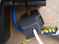
I had an Efergy Elite electricity monitor which I received as a gift a few years ago. The product comprises a current transformer sensor which clips on to the utility meter outside. This transmits a power reading every 6 seconds over a 433MHz radio to the receiver unit indoors. The receiver has a LCD which displays instantaneous power use, and hourly, daily weekly averages (and other less interesting stuff like CO2 emissions). Photos of the sensor, receiver and internal electronics are here. There is no computer interface to tap into this data, so one needed to be hacked in.
There is a block diagram of my solution:
Looking at the receiver unit electronics, there is a test pad located near the radio part of the PCB. (The A72C01AUF chip to the bottom left of the test pad does all the radio heavy lifting both in the sensor and receiver).
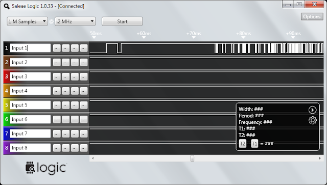
Looking at the signal at this point with an oscilloscope one can see there is burst of logic level (0/5V) signals every 6 seconds. This would seem to be the base band output from the radio. An oscilloscope isn't the most useful tool for decoding digital IO if there are more than a few bits involved. I put a recently purchased Saleae 'Logic' (logic analyzer) on the task and this is what the signal looked like:
This signal didn't seem to make much sense. So I also simultaneously recorded the sensor's digital input line to the transmitter (pin 18 on the sensor's MCU – which by the way is a GSSP 22682X01 – a difficult chip to locate a datasheet for).
Thanks to the logic analyzer's big picture it seems there is an initial block of what looks like random noise preceding the actual data (I'm guessing this is just noise from the radio transmitter powering up).
Now looking more closely at the actual data:
The data is encoded using a digital equivalent of Frequency Shift Keying (FSK). A logic 0 is represented by three long pulses of 2ms duration in total (a low frequency) and a logic 1 by 4 shorter pulses totaling 2ms also (a high frequency).
Decoding this could be achieved with analog circuitry but this would involve a handful of (relatively) expensive passive components. Instead I chose a pure digital technique. I used a simple pattern matching algorithm to look for 3 successive long pulses or 4 successive short pulses and ignore anything else (code appended below).
From bits to bytes
So now I have a string of logic '0's and '1's. The next problem is to determine where the byte boundaries are.
Fortunately each data packet starts with the following 4 bytes: 0xAB 0xAB 0xAB 0x2D. This helps with synchronization. When looking for the start of data I shove the bits into a shift register until I get a byte value of 0xAB. I take all subsequent bits as groups of 8 to form the bytes of data. After the first 0xAB I ignore all subsequent byte values of 0xAB until I get a 0x2D. I am now at the start of the packet payload.
A typical packets look like this:
So in summary, each packet comprises a unique sensor address, the sampling rate, a battery low flag and 3 x 12 bit ADC values for each of the sensor's three inputs (normal domestic power is single phase, so only one input is used. A three phase system would use all three inputs) and finally a checksum of the contents of the packet for data integrity.
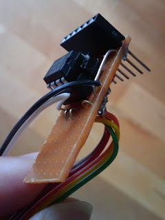
I soldered a small (12F675) PIC MCU to a piece of veroboard (pictured right) and wrote a program to decode the baseband signal from the radio and convert that to actual data.
The PIC code used to decode the radio baseband signal is listed below (this excerpt is not the full PIC application – contact me if you need the lot):
The next problem is to figure how to translate these ADC values to Amps (and by multiplying by 230V to Watts) and how to feed this data to a database for recording and visualization. These will be covered in subsequent posts.
Related Links
Updates to post:
This series of posts describes how I hacked a low cost (€37 from Maplin) Efergy Elite electricity monitor to obtain real time power use data and to record and chart this data with the aim of understanding how electricty is used in the home and how to reduce consumption.
Describing the entire solution in one go is going to result in an excessively long post, so I'm going to break this into several parts over the next few weeks. In this post I'll describe the process involved in getting access to the raw data from the sensor unit.
The term 'smart' in the title is a misnomer. All I want to do here is record real time (at least several samples per minute) power use into a computer system. A true 'smart' meter will do telemetering, facilitate demand based tariffs, feed-in tariffs etc.
The problem with low cost energy monitors is you only get the current instantaneous usage and perhaps hourly, daily and weekly averages.
What I want is something that looks like this:
In this chart I can see my coffee machine (left on accidentally), the oven (not much I can do about that) and the fridge. From that chart I can figure the base load due to broadband router, WiFi access point, DVR etc and work out the average use of my fridge (by estimating the duty cycle and subtracting the power level while on from the base load).
So, how did I arrive at this chart?
I had an Efergy Elite electricity monitor which I received as a gift a few years ago. The product comprises a current transformer sensor which clips on to the utility meter outside. This transmits a power reading every 6 seconds over a 433MHz radio to the receiver unit indoors. The receiver has a LCD which displays instantaneous power use, and hourly, daily weekly averages (and other less interesting stuff like CO2 emissions). Photos of the sensor, receiver and internal electronics are here. There is no computer interface to tap into this data, so one needed to be hacked in.
There is a block diagram of my solution:
Looking at the receiver unit electronics, there is a test pad located near the radio part of the PCB. (The A72C01AUF chip to the bottom left of the test pad does all the radio heavy lifting both in the sensor and receiver).
Looking at the signal at this point with an oscilloscope one can see there is burst of logic level (0/5V) signals every 6 seconds. This would seem to be the base band output from the radio. An oscilloscope isn't the most useful tool for decoding digital IO if there are more than a few bits involved. I put a recently purchased Saleae 'Logic' (logic analyzer) on the task and this is what the signal looked like:
This signal didn't seem to make much sense. So I also simultaneously recorded the sensor's digital input line to the transmitter (pin 18 on the sensor's MCU – which by the way is a GSSP 22682X01 – a difficult chip to locate a datasheet for).
Thanks to the logic analyzer's big picture it seems there is an initial block of what looks like random noise preceding the actual data (I'm guessing this is just noise from the radio transmitter powering up).
Now looking more closely at the actual data:
The data is encoded using a digital equivalent of Frequency Shift Keying (FSK). A logic 0 is represented by three long pulses of 2ms duration in total (a low frequency) and a logic 1 by 4 shorter pulses totaling 2ms also (a high frequency).
Decoding this could be achieved with analog circuitry but this would involve a handful of (relatively) expensive passive components. Instead I chose a pure digital technique. I used a simple pattern matching algorithm to look for 3 successive long pulses or 4 successive short pulses and ignore anything else (code appended below).
From bits to bytes
So now I have a string of logic '0's and '1's. The next problem is to determine where the byte boundaries are.
Fortunately each data packet starts with the following 4 bytes: 0xAB 0xAB 0xAB 0x2D. This helps with synchronization. When looking for the start of data I shove the bits into a shift register until I get a byte value of 0xAB. I take all subsequent bits as groups of 8 to form the bytes of data. After the first 0xAB I ignore all subsequent byte values of 0xAB until I get a 0x2D. I am now at the start of the packet payload.
A typical packets look like this:
AB, AB, AB, 2D, 00, 0B, 5A, 40, 98, 00, 02, 00, 41After some experimentation this is what I believe the packet consists of:
| 0 | Sync, always 0xAB |
| 1 | Sync, always 0xAB |
| 2 | Sync, always 0xAB |
| 3 | Sync end, always 0x2D |
| 4 | ? always 0x00 |
| 5 | Device address high byte (always 0x0D for my device) |
| 6 | Device address low byte (always 0x5A for my device) |
| 7 | sbssaaaa where s = bits of sampling period, b = battery low indicator (0 = low) and aaaa is the upper 4 bits of sensor A. 0-00---- = 6s sampling, 1-01---- = 12s sampling, 0-10---- = 18s sampling. It's odd that ‘b’ is sandwiched in among s bits. |
| 8 | Least significant 8 bits of sensor input A (nearest MCU edge of board) |
| 9 | ? probably upper 4 bits of sensor B and C. |
| 10 | Least significant 8 bits of sensor input B (middle) |
| 11 | Least significant 8 bits of sensor input C |
| 12 | Checksum (arithmetical sum of bytes 4 - 11). |
So in summary, each packet comprises a unique sensor address, the sampling rate, a battery low flag and 3 x 12 bit ADC values for each of the sensor's three inputs (normal domestic power is single phase, so only one input is used. A three phase system would use all three inputs) and finally a checksum of the contents of the packet for data integrity.
I soldered a small (12F675) PIC MCU to a piece of veroboard (pictured right) and wrote a program to decode the baseband signal from the radio and convert that to actual data.
The PIC code used to decode the radio baseband signal is listed below (this excerpt is not the full PIC application – contact me if you need the lot):
The next problem is to figure how to translate these ADC values to Amps (and by multiplying by 230V to Watts) and how to feed this data to a database for recording and visualization. These will be covered in subsequent posts.
Related Links
Updates to post:
- 4 Jan 2011: Added related links section.
- 16 Apr 2011: Part 2 published.
#include#include "efergy_config.h" #include "efergy_elite_decode.h" byte getPulseWidth(); byte getBit (); byte getByte (); void resync(); byte t3,t4,tm; /** * Decode baseband radio signal from Efergy Elite receiver. * * Packet consists of a radio preamble of what seems * like random noise for about 200ms followed by a quiet period * of 100ms followed by data for 200ms. Encoding is a FSK type * scheme. * Logic 0 is represented by 3 cycles of "low" frequency square * wave (period 8t per cycle). * Logic 1 is represented by 4 cycles of "high" frequncy square * wave (period 6t per cycle). * Logic 0 and Logic 1 have the same period of 24t which is * very approx 2ms [confirm]. Ie t ~= 83 microseconds. * * +---+ +---+ +---+ * | | | | | = Logic 0 * +--| +---+ +---+ * +--+ +--+ +--+ +--+ * | | | | | | | = Logic 1 * +-+ +--+ +--+ +--+ * * Decoding this not but looking at frequency, but looking * for 3 long pulses in succession or 4 short pulses. * * Data has 3 bytes of synchronization: 0xAB, 0xAB, 0x2D. * Look initially for 0xAB to get byte boundary synchronization. * Then look for 0x2D to flag start of actual data. * * All inter-pulse calculation must be complete * within 64x5 microseconds ie ~ 300 microseconds or 300 instructions @ 4MHz) */ byte decodeEfergy(unsigned char *buf) { byte i,bitc=0, bytec=0, b=0; byte t,pt; //byte bufIndex=0; unsigned int rt=0; t3=0x1a; // short pulse duration of 3t t4=0x23; // long pulse duration of 4t tm = 0x1e; // mean of short and long pulse, ie 3.5t resync: // Look for sync bit sequence // TODO: update: just look for AB followed by 2D. // Get byte boundary sync while (b != 0xAB) { b = (b<<1) | getBit(); } for (i = 0; i < 8; i++) { b = (b<<1) | getBit(); } if (b != 0xAB) { goto resync; } for (i = 0; i < 8; i++) { b = (b<<1) | getBit(); } if (b != 0x2D) { goto resync; } b=0; // 9 bytes left to retrieve do { b = (b<<1) | getBit(); bitc++; if (bitc == 8) { buf[bytec++] = b; b=bitc=0; } } while (bytec < 9); // Calculate checksum byte cs = 0; for (i = 0; i < 8; i++) { cs += buf[i]; } // Display checksum fail if they don't match if (cs != buf[8]) { return 4; } return 0; } byte getByte () { byte i,b; for (i = 0; i < 8; i++) { b = (b<<1) | getBit(); } return b; } byte getBit () { char t; byte nshort=0,nlong=0; while (1) { t = getPulseWidth(); if ( t < tm) { nshort++; } else { nlong++; } // Check for anomalous condition if ( (nshort>0) && (nlong>0) ) { nshort=nlong=0; if ( t < tm) { nshort=1; } else { nlong=1; } } if (nshort == 4) { return 1; } if (nlong == 3) { return 0; } } } byte getPulseWidth() { byte t=0; while (RADIOBB_PIN) { CLRWDT(); } while ( ! RADIOBB_PIN) { t++; } return t; } void resync () { byte pt,t; restart_resync: // Can have either 3t (short) or 4t (long) pulse. Get pulses of // two different lengths. 3t is the short pulse, 4t is the long one. pt = getPulseWidth(); do { t = getPulseWidth()+2; } while (t - pt < 4); t -= 2; if (pt < t) { t3 = pt; t4 = t; } else { t3 = t; t4 = pt; } if (t4 < 0x1A) { //TXREG='s'; goto restart_resync; } if (t4 > 0x30) { //TXREG='l'; goto restart_resync; } // Didn't have to do this at the sensor, but receiver has a lot more incoming crud if ( ((t4>>2)*3 ^ t3) & 0b11111100 ) { // (t4/4)*3 ~= t3 (ignoring 2 LSB of precision) //TXREG='?'; goto restart_resync; } // tm is mean of t3 and t4 tm = (t3+t4)>>1; byte b=0; // Look for sync bit sequence while (b != 0xAB) { b = (b<<1) | getBit(); } }
Sunday, August 22, 2010
Mapping cell coverage in the Glengarriff Valley
As a follow up to my Froyo on a Stick experiment, I wondered why the signal in the Glengarriff valley was so spotty and where it was coming from.
I found two apps in the Android Market which report and log cell data: "Antennas" and "RF Signal Tracker". I enabled the logging on both apps and cycled around the area. In the immediate vicinity of where I was staying the signal was almost non-existent. But not far away there was acceptable signal levels.
It turns out these apps not only record cell ID, and signal strength, but also (from somewhere?!) downloads the location of the cell towers.
Plotting this data on Google Maps yielded some answers. It turns out the tower was to the north and not the east as I had originally thought. The signal into the valley was being attenuated by a ridge of the Caha Pass a little higher than the tower (despite no line-of-sight, diffraction of radio waves allows some signal through). On either side of the ridge were peaks exceeding 400m elevation: so it would appear this constrained reception to a beam within the valley.
My data would appear to confirm this. Within the yellow wedge it seemed possible to get a signal (red dots indicate points where I could connect). In the grey wedge a signal was mostly not obtainable.
Data acquisition and visualization
I ran both "Antennas" and "RF Signal Strength" together. The UI in the latter app wasn't very good... it was slow to respond and would frequently hang. Fortunately the logging function worked. The "Antennas" UI on the other hand appeared to work better, but failed to log much data.
The data from "RF Signal Strength" looks like this:
I wrote a script (Java + Javascript) to plot this on Google Maps Terrain layer. Then copied a screen grab into Google Draw Tool to annotate.
I found two apps in the Android Market which report and log cell data: "Antennas" and "RF Signal Tracker". I enabled the logging on both apps and cycled around the area. In the immediate vicinity of where I was staying the signal was almost non-existent. But not far away there was acceptable signal levels.
It turns out these apps not only record cell ID, and signal strength, but also (from somewhere?!) downloads the location of the cell towers.
Plotting this data on Google Maps yielded some answers. It turns out the tower was to the north and not the east as I had originally thought. The signal into the valley was being attenuated by a ridge of the Caha Pass a little higher than the tower (despite no line-of-sight, diffraction of radio waves allows some signal through). On either side of the ridge were peaks exceeding 400m elevation: so it would appear this constrained reception to a beam within the valley.
My data would appear to confirm this. Within the yellow wedge it seemed possible to get a signal (red dots indicate points where I could connect). In the grey wedge a signal was mostly not obtainable.
Data acquisition and visualization
I ran both "Antennas" and "RF Signal Strength" together. The UI in the latter app wasn't very good... it was slow to respond and would frequently hang. Fortunately the logging function worked. The "Antennas" UI on the other hand appeared to work better, but failed to log much data.
The data from "RF Signal Strength" looks like this:
_id,latitude,longitude,rssi,logdate,mcc,mnc,lac,cellid,site_lat,site_lng,tech,ber,callstate,roaming
1,51766086,-9613348,-99,14 Aug 2010 13:56:03,272,1,47,11011,52181474,-1357067,GPRS,-1,IDLE,NO
2,51766086,-9613348,-99,14 Aug 2010 13:56:26,272,1,47,11011,52181474,-1357067,GPRS,-1,IDLE,NO
3,51766086,-9613348,-99,14 Aug 2010 13:56:27,272,1,47,11011,52181474,-1357067,GPRS,-1,IDLE,NO
I wrote a script (Java + Javascript) to plot this on Google Maps Terrain layer. Then copied a screen grab into Google Draw Tool to annotate.
Froyo on a stick
When faced with an impossibly weak cell signal and an Android phone, what can you do?
Recently while on holiday in the Glengarriff valley, west County Cork, I was faced with this problem.
Android 2.2 (aka "Froyo") has a cool feature that allows the phone to become a WiFi access point. This is intended to be a convenient way to allow a laptop to use the phone's internet connection. Normally the phone would be sitting right next to the laptop. But it doesn't have to be so close. A line-of-sight range of more than 20 meters is possible.
At my location I was getting tantalizing brief connections to the cell network (Vodafone IE), and occasionally the odd GPRS IP packet might make it through. But nothing close to usable.
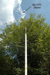
As a rule of thumb you can improve a weak radio signal by raising the height of the antenna. So I got several planks of wood. Strapped them together with duct tape to form a make shift antenna mast about 8m in height. I switched the mobile hotspot feature on, taped the phone to the top of the mast and raised it.
And sure enough I was able to get a usable [*] connection where none existed before.
[*] The connection was only GPRS and there was still packet loss... but sufficient to get email in and out. Perhaps another few meters might have made the difference.
Recently while on holiday in the Glengarriff valley, west County Cork, I was faced with this problem.
At my location I was getting tantalizing brief connections to the cell network (Vodafone IE), and occasionally the odd GPRS IP packet might make it through. But nothing close to usable.
As a rule of thumb you can improve a weak radio signal by raising the height of the antenna. So I got several planks of wood. Strapped them together with duct tape to form a make shift antenna mast about 8m in height. I switched the mobile hotspot feature on, taped the phone to the top of the mast and raised it.
And sure enough I was able to get a usable [*] connection where none existed before.
[*] The connection was only GPRS and there was still packet loss... but sufficient to get email in and out. Perhaps another few meters might have made the difference.
Saturday, July 31, 2010
Leaving the immersion water heater on – mildly expensive or financial ruin?
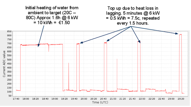
I recently stumbled across this blog post about the horrors of forgetting to switch off the immersion water heater. Now that I have my real time energy monitor I thought it would be interesting to see how financially crippling "leaving the immersion on" would actually be.
Here is the result:
Conclusion
There is two phases in "leaving the immersion on" phenomenon:
However if left on indefinitely and no hot water is consumed, the only additional energy required is to keep the cylinder at the target temperature. With modern well insulated cylinders it's not that much (relatively speaking). In my case a 5 minute burst of 6kW every 1.5 hours. That works out at about €1.20 / day or €8.40 / week assuming no hot water is consumed.
The blog post referred to above mentioned the ESB (power utility company) estimated the cost to be about €20 / week. Allowing for colder weather and reasonable hot water use that sounds about right. (I am assuming electricity costs €0.15/kWh unit.)
BTW: physics sanity check: my cylinder is 117 liters. Heating water from 20C to 80C ie ΔT of 60C. Requires 60 x 4.4kJ x 117 = 30888kJ. At 6kW that requires 30888/6 seconds = 5148 seconds = 1.43 hours. Which approximately squares with what I'm seeing above.
Here is the result:
Conclusion
There is two phases in "leaving the immersion on" phenomenon:
- The initial heating of the water cylinder from cold to target temperature (set by the thermostat in the heater)
- Short bursts of about 5 minutes every hour or so to keep the water at target temperature
However if left on indefinitely and no hot water is consumed, the only additional energy required is to keep the cylinder at the target temperature. With modern well insulated cylinders it's not that much (relatively speaking). In my case a 5 minute burst of 6kW every 1.5 hours. That works out at about €1.20 / day or €8.40 / week assuming no hot water is consumed.
The blog post referred to above mentioned the ESB (power utility company) estimated the cost to be about €20 / week. Allowing for colder weather and reasonable hot water use that sounds about right. (I am assuming electricity costs €0.15/kWh unit.)
BTW: physics sanity check: my cylinder is 117 liters. Heating water from 20C to 80C ie ΔT of 60C. Requires 60 x 4.4kJ x 117 = 30888kJ. At 6kW that requires 30888/6 seconds = 5148 seconds = 1.43 hours. Which approximately squares with what I'm seeing above.
Friday, July 30, 2010
What most energy monitors don't tell you!
I received a Efergy Elite energy monitor (sold in Maplin and other retailers) as a Christmas gift few years go. The Elite provides current use, daily and weekly average and all that green CO₂ nonsense. While useful for tracking down unnecessary drains it doesn't give you a true picture of electricity use throughout the day.
Despite getting all this juicy data every 6 seconds the Elite won't share it with you. There is no computer port. So I hacked it.
I soldered a wire on the baseband signal from the radio receiver, into a cheap little PIC MCU for some decoding and at the other end a stream of numbers every 6 seconds. Bung that into a graphing package and you get a chart like that above.
[*] Actually it can only sense current. So you assume that the supply is at a constant 230V rms and you can calculate the power (power = V*I). It's not accurate enough for billing, but certainly good enough for consumer energy monitoring.
Thursday, July 1, 2010
Unique address for wireless sensors
When designing wireless sensors any sensible communications protocol will feature a device address so that multiple instances of the setup can exist in the same space.
So how do you ensure that wireless devices have a unique address? One approach is to embed a fixed serial number in every device (much like the 48 bit WiFi or Bluetooth MAC address). This requires that each device is programmed with the number at manufacture time.
Another other approach is to use a random number generator to assign an address when the device is configured. For consumer devices is normally involves pressing an associate button on the sensor device for a few seconds.
It is not possible for a CPU to generate a genuine random number without outside help. Fortunately there is a workaround, which utilizes one of the best sources of randomness there ever existed: a human.
My approach (which I suspect is common, but I cannot find any references to it) is to generate a random number when the device is associated using the duration of the associate button press as the source of the random number.
The idea is to time the duration of the button press with as much resolution as possible (eg in microseconds). Then take this duration modulo the size of your address space and you have a pretty good random number.
For example, let’s assume we can time the button press with µs precision and that we are looking for a random 16 bit address (ie a number between 0 and 65535). The clock will cycle through this entire address space in just under 66ms – less than the time that a typical human will take to press a button.
Let's look at some real data. I rigged a micro switch on a pin on the Arduino and wrote a simple timing loop. I pressed the micro switch about 1000 times in succession.
You can see that the typical micro switch press lasted about 100ms +/- 50ms. As the experiment progressed I started getting bored so you will notice a slight decrease in button press duration as impatience set in. A histogram view of this data looks like this:
A normal distribution as one would expect. Now if we take these time values modulo 2^16 (65536) we have a distribution that looks like this:
Nicely spread across the entire address space, with a slight bias in the 30000 - 60000 region, but good enough.
Tuesday, June 29, 2010
PIC Serial IO Example
I’ve been working on the PIC firmware for my ABPM project over the past few weeks and I thought it would be useful to combine many of the tips and tricks I learned into a little demo C program. I hope this will help others get up and running fast with similar applications.
The key features of this program are:
Interfacing a PIC to a PC using Serial IO
Serial IO is a theoretically a very simple way of communicating with a PIC. Most PICs have hardware support for this protocol and until a few years ago most PCs had one or more serial ports (in the form of a 9 pin D connector RS232 port). Unfortunately even though the PC and the PIC speak the same serial IO ‘language’, they do so at incompatible voltage levels, so a direct connection is not possible. There are hacks involving resistors, but it doesn’t always work. The easiest ‘correct’ solution is to use the MAX232 chip which converts logic to RS232 voltage levels.
Leaving aside the voltage level problem, a more serious problem is that RS232 ports are increasingly rare having been replaced by the substantially faster and more flexible USB. Interfacing directly with USB is not trivial without the use of a support chipset such as the FTDI FT232RL.
So there are two approaches to achieve PC connectivity:
Configuring a Bus Pirate to act as serial IO bridge
Connect to the Bus Pirate with a terminal emulator (eg minicom on Linux). At the Bus Pirate prompt enter:
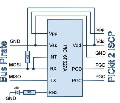
Because we have chosen high to be represented by a high impedance state, a pull up resistor (eg 22K) to Vdd is required (see schematic).
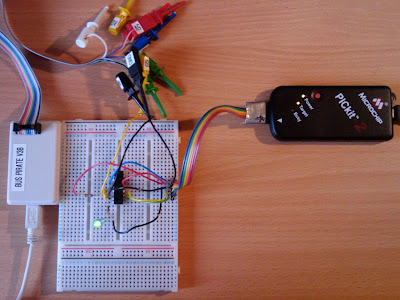
Connect the Bus Pirate ground to Vss/GND, MISO to PIC TX and MOSI to PIC RX. Finally select the bridge mode macro: (1) In response to message “UART bridge. Space continues, anything else exits” press the SPACE key. Note: you can only exit this mode by power cycling the device.
Programming the PIC
A socket programmer can be used such as the Velleman K8048. But for development work the constant plugging and unplugging of the chip is a colossal waste of time and will quickly damage the chip’s pins.
Configuring a PICkit 2 as in in-circuit programmer is a far better option. In this configuration the 5 pin ISCP port (Vpp, Vdd, GND, PGD, PGC) is connected to corresponding pins on the PIC. If the Vpp pin is also used in your application (it can double as RA5 or MCLR) a protective diode should be utilized to protect your application circuitry from the ~ 13V programming voltage.
The ISCP port also optionally provides power to the circuit but there are current limits to be aware of: 25mA in the case of a PICkit2. Exceeding that may cause the USB port to switch off (although permanent damage is unlikely). Please refer to chapter 3 of the “PICkit™ 2 Programmer and ICSP™” guide downloadable from http://www.microchip.com for details on the operation of the ICSP port.
Loading the program from Linux
Download the PICkit2 command line Linux utility from http://www.microchip.com/
You can power off the PIC at any time with this command:
and power it back up with:
Loading the program from Windows
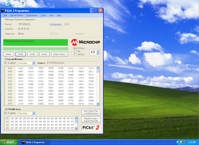
From PICkit 2 Programmer (free download from http://www.microchip.com) choose File -> Import Hex. Then click the “Write” button and if all goes well the status window should turn green with the message “Programming Successful”.
Running the program
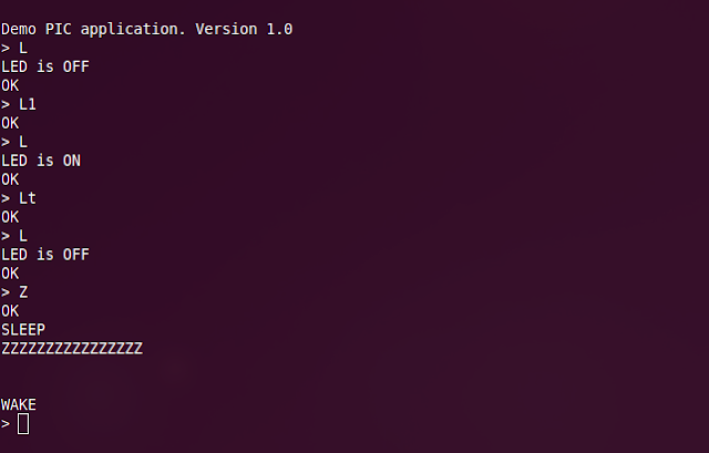
After successful upload of the firmware to the PIC, all going will you should see a welcome message “Demo PIC application. Version 1.0” on the serial port. You can now enter commands at the prompt. These commands are implemented in the execCmd() function. Additional commands can be added as programming space allows. A command comprises a single letter (upper or lower case) followed by optional arguments and terminated by the RETURN key.
Command summary:
Command error codes:
On successful command execution an “OK” message will be displayed. If an error is encountered “ERR” followed by an error number will be displayed.
Compiling the C code
As it stands this application doesn’t do anything very useful. You will need to edit the C to customize for your application.
You will need the MPLAB IDE from Microchip (a free download at http://www.microchip.com). This is a Windows application, but will run under Wine emulation on Linux (just run the installer in Wine).
Download the ZIP archive from http://wombat.ie/software/electronics/PIC/ and unpack it into a directory.
In MPLAB chooise Project -> Open... from the menu and navigate to the directory into which you unpacked the ZIP archive. Choose the SIODemo.mcp project.
Select Configure -> Select Device... and ensure you have the correct target chip selected.
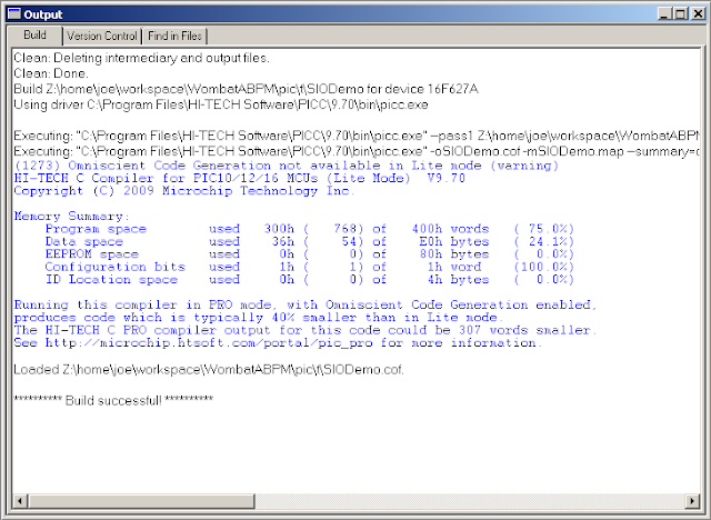
Key CTRL-F10 (or Project -> Project Rebuild from the menu) to rebuild everything.
If all goes well you should have SIODemo.hex in the same directory. Upload the HEX file to the device with the programmer.
The Code
The code and compiled HEX file can be downloaded from http://wombat.ie/software/electronics/PIC/
The key features of this program are:
- control and configuration via serial IO cable which can be detached when not required
- very low power consumption – must run on batteries and last months
- simple timing functions (eg awake every 20 minutes, take a reading, go back to sleep)
- a PIC 16F627A, 16F628A or equivalent. Other PICs of with similar functionality may work but a re-compile many be required. If ordering PICs make sure you order it in a plastic DIP package.
- a prototyping breadboard
- some way to interface logic voltage level serial IO to a computer (a discussion on this in a moment)
- a PIC programmer (eg PICkit2), ideally configured to program in-circuit
- one LED, a few resistors and some suitable jumper wires for the breadboard
Interfacing a PIC to a PC using Serial IO
Serial IO is a theoretically a very simple way of communicating with a PIC. Most PICs have hardware support for this protocol and until a few years ago most PCs had one or more serial ports (in the form of a 9 pin D connector RS232 port). Unfortunately even though the PC and the PIC speak the same serial IO ‘language’, they do so at incompatible voltage levels, so a direct connection is not possible. There are hacks involving resistors, but it doesn’t always work. The easiest ‘correct’ solution is to use the MAX232 chip which converts logic to RS232 voltage levels.
Leaving aside the voltage level problem, a more serious problem is that RS232 ports are increasingly rare having been replaced by the substantially faster and more flexible USB. Interfacing directly with USB is not trivial without the use of a support chipset such as the FTDI FT232RL.
So there are two approaches to achieve PC connectivity:
- Use USB <--> RS232 adapter (about €25) at the PC end and a MAX232 for voltage conversion at the PIC end
- Bypass the whole RS232 voltage level problem by using a Bus Pirate to act as a bridging device. The Bus Pirate costs about €25 and will avoid the complication of adding a MAX232 to your project.
Configuring a Bus Pirate to act as serial IO bridge
Connect to the Bus Pirate with a terminal emulator (eg minicom on Linux). At the Bus Pirate prompt enter:
m(return) (select mode)
3(return)  (select UART mode)
6(return)  (select baud rate of 19200)
(return) (select 8 bits, no parity - default)
(return) (select 1 stop bit - default)
(return) (select idle 1 - default)
(return) (select open drain, high = high impedance, low = GND)
Because we have chosen high to be represented by a high impedance state, a pull up resistor (eg 22K) to Vdd is required (see schematic).
Connect the Bus Pirate ground to Vss/GND, MISO to PIC TX and MOSI to PIC RX. Finally select the bridge mode macro: (1)
Programming the PIC
A socket programmer can be used such as the Velleman K8048. But for development work the constant plugging and unplugging of the chip is a colossal waste of time and will quickly damage the chip’s pins.
Configuring a PICkit 2 as in in-circuit programmer is a far better option. In this configuration the 5 pin ISCP port (Vpp, Vdd, GND, PGD, PGC) is connected to corresponding pins on the PIC. If the Vpp pin is also used in your application (it can double as RA5 or MCLR) a protective diode should be utilized to protect your application circuitry from the ~ 13V programming voltage.
The ISCP port also optionally provides power to the circuit but there are current limits to be aware of: 25mA in the case of a PICkit2. Exceeding that may cause the USB port to switch off (although permanent damage is unlikely). Please refer to chapter 3 of the “PICkit™ 2 Programmer and ICSP™” guide downloadable from http://www.microchip.com for details on the operation of the ICSP port.
Loading the program from Linux
Download the PICkit2 command line Linux utility from http://www.microchip.com/
pk2cmd -PPIC16F627A -FSIODemo.hex -M -T -R
You can power off the PIC at any time with this command:
pk2cmd -PPIC16F627A -W
and power it back up with:
pk2cmd -PPIC16F627A -T -R
Loading the program from Windows
From PICkit 2 Programmer (free download from http://www.microchip.com) choose File -> Import Hex. Then click the “Write” button and if all goes well the status window should turn green with the message “Programming Successful”.
Running the program
After successful upload of the firmware to the PIC, all going will you should see a welcome message “Demo PIC application. Version 1.0” on the serial port. You can now enter commands at the prompt. These commands are implemented in the execCmd() function. Additional commands can be added as programming space allows. A command comprises a single letter (upper or lower case) followed by optional arguments and terminated by the RETURN
Command summary:
L no params Query LED state. Will return “ON” or “OFF”.
L ‘0’ or ‘1’ Turn LED on or off respectively.
L ‘t’ Toggle LED state
R no params Reset device
T no params Return toc timer
Z no params Put device to sleep. Will confirm with “SLEEP” message. Hit any key to wake device. Will display “WAKE” message on waking.
Command error codes:
On successful command execution an “OK” message will be displayed. If an error is encountered “ERR” followed by an error number will be displayed.
ERR 2 Unrecognized command
ERR 3 Bad command parameters
Compiling the C code
As it stands this application doesn’t do anything very useful. You will need to edit the C to customize for your application.
You will need the MPLAB IDE from Microchip (a free download at http://www.microchip.com). This is a Windows application, but will run under Wine emulation on Linux (just run the installer in Wine).
Download the ZIP archive from http://wombat.ie/software/electronics/PIC/ and unpack it into a directory.
In MPLAB chooise Project -> Open... from the menu and navigate to the directory into which you unpacked the ZIP archive. Choose the SIODemo.mcp project.
Select Configure -> Select Device... and ensure you have the correct target chip selected.
Key CTRL-F10 (or Project -> Project Rebuild from the menu) to rebuild everything.
If all goes well you should have SIODemo.hex in the same directory. Upload the HEX file to the device with the programmer.
The Code
The code and compiled HEX file can be downloaded from http://wombat.ie/software/electronics/PIC/
/**
 * Example of a serial IO shell for a PIC.
 * Rev 27 June 2010.
 * (c) 2010 Joe Desbonnet, jdesbonnet@gmail.com.
 * Distributed under the "Simplified BSD License".
 *
 * This example is intended as a starting point for writing low power PIC apps
 * that need to be controlled over a serial port.
 *
 * This program will listen on the PIC's serial port for commands sent from a
 * human user via a terminal emulator or commands issued from another application.
 * In this example commands are L, L0, L1, Lt (LED status, off, on, toggle
 * respectively, R (reset), T (get sleep clock 'tocs'), Z (go to sleep). See
 * comments at execCmd() function for more details.
 *
 * During sleep mode the device uses very little power (micro watts) and can
 * stay powered on 2 x AAA batteries for months.
 *
 * Tested with 'Lite' version of HiTech C compiler for PIC on target
 * platform PIC16F627A and 16F628A. This code should be read in together with the
 * PIC datasheet which can be downloaded from http://www.microchip.com
 *
 * This program occupies most of the available space of a 16F627A. However the
 * use of stdio functions and liberal use of printf() accounts for a large portion
 * of the space used. For practical apps long string messages are not required and
 * the use of printf() can often be avoided.
 *
 * It is assumed that there is a LED on RB3 (pin 9) which must have a limiting
 * resistor of ~ 500 ohms. The serial port RX and TX and connected to pins
 * 7 and 8 respectively. Also the RX line (pin 7) and INT (pin 6) are tied together
 * to facilitate wake on serial port activity.
 *
 * NB: Do not connect RX and TX directly to RS232 as the voltage levels (typically
 * -15V to -3V for logic 1 and +3V to +15V for logic 0) are not compatible
 * with PIC logic levels 0/ ~5V.
 *
 * Simplified schematic:
 *
 *          +-----------+
 *          |   PIC     |
 *          |16F627/8(A)|
 *          |           |
 * GND------|Vss     Vdd|------ 2 - 5V
 *          |           |
 *      +---|INT        |
 *      |   |           |
 *  ----+---|RX         |
 *          |           |
 *  --------|TX         |
 *          |           |
 *    +-----|RB3        |
 *    |     +-----------+
 *  500ohm
 *    |
 *   LED
 *    |
 *   GND
 *
 * Not shown: logic <--> RS232 conversion, optional crystal resonator.
 *
 * It is generally recommended that unused input pins are tied either high
 * or low through a ~ 10K resistor. However I have found that if setup correctly
 * (specifically MCLR and LVP are disabled) unused pins can be left floating.
 *
 */

#include <htc.h>
#include "stdio.h"

// Bit manipulation macros
#define BIT(x)   (1 << (x))
#define SETBIT(p,b) (p) |= BIT(b)
#define CLRBIT(p,b) (p) &= ~BIT(b)
#define TOGBIT(p,b) (p) ^= BIT(b)
#define TSTBIT(p,b) (p) & BIT(b)

/*
Configuration Word:

Oscillator
--------------
HS:    High speed external oscillator
INTIO: Internal oscillator (4MHz)

Remember to set FOSC accordingly.


Watch Dog Timer (WDT)
--------------
WDTEN: Watch dog timer enable
WDDIS: Disable watch dog timer

When enabled a SLEEP operation will resume at the next instruction when the timer
rolls over.  Otherwise SLEEP can only be interrupted by an external event. It takes
about 2 seconds for the timer to roll over. A simple low-accuracy sleep clock can
be made by counting the SLEEP/wake cycles. The device can be awoken after a set
period of time this way (not implemented in this version). When the WDT is enabled
a WDT roll over while awake will cause a device reset which we don't want in the
application. So it's important that the WDT is cleared periodically by calling
CLRWDT().

Other features
--------------

Unused features are disabled.

PWRTDIS:   Power up timer disable
BODIS:     Brownout reset disable
UNPROTECT: Code protection disable
MCLRDIS:   Master Clear disable. Prevents spontaneous resets if MCLR left floating.
LVPDIS:    Low Voltage Programming disable. Prevents problems if RB4/PGM pin left floating.

A note about MCLR and LVP features: if you do enable those features, it is vital
that you *don't* allow MCRL and PGM pins to float. Tie them high or  low via a
~ 10K resistor. If you don't you will probably experience spontaneous  resets
and intermittent failures.

*/

__CONFIG(INTIO & WDTEN & PWRTDIS & BORDIS  & UNPROTECT & MCLRDIS & LVPDIS);

// Oscillator frequency. Set to 4000000UL if using internal oscillator. Else
// set to the external crystal frequency.
//#define FOSC 10000000UL
#define FOSC 4200000UL

// Desired serial port baud rate. In theory any value is possible, but the
// traditional values are 300, 1200, 2400, 4800, 9600, 19200, 38400, 112500
// [Note about max speed, 19200 max with internal 4MHz osc?]
#define BAUD 19200

#define BUF_LEN 8  // Define the length of the command buffer
#define LED_PIN RB3  // Define LED pin.
#define LED_TRIS TRISB3 // Define LED tri-state bit (for configuration to output)


// Function prototypes
unsigned char execCmd();
void prompt();
void crlf();

// Flags shared with ISR. For convenience using an entire 8 bit value to represent
// a single flag. A value 1 being set, 0 being clear. This is wasteful and you may
// want to use individual bits of a one general flags variable if space becomes tight.
volatile unsigned char sleepMode; // set to 1 if currently SLEEPing as much as possible
volatile unsigned char wakeFlag; // set to 1 by ISR to signal to main loop to wake up
volatile unsigned char cmdFlag;  // set to 1 by ISR to signal to main loop that ENTER was received

volatile unsigned char bufp;  // indicates the position of the next free char in the buffer
char buf[BUF_LEN];     // command buffer

unsigned int toc = 0;    // initialize our simple clock to 0

/**
 * Initialize hardware
 */
void init(void) {

 //
 // Configure serial port
 //

 // Serial Port Baud Rate Generator. Ref sect 12.1
 // "USART Baud Rate Generator (BRG)", page 75 of datasheet.
 SPBRG = (int)( FOSC / (16UL * BAUD) - 1 );

 // Receive Status register
 // 1--- ----  SPEN (Serial Port Enable)
 // ---1 ----  CREN (Continuous Receive Enable)
 RCSTA = 0x90;

 // Transmit Status register
 // --1- ----  TXEN (Transmit Enable)
 // ---- -1--  BRGH (High baurd rate select)
 TXSTA = 0x24;


 //
 // Configure interrupts
 //

 GIE  = 1;      // Enable all unmasked interrupts
 PEIE = 1;      // Enable all unmasked peripheral interrupts
 INTE = 1;      // Enable external interrupt on RB0 (also tied to RX for wake-on-RX)
 RCIE = 1;      // Enable RX interrupt (only works while awake)


 //
 // Configure LED pin as output
 //

 LED_PIN = 0;     // Set to off on latch
 LED_TRIS = 0;     // Set pin as output

}


void main(void){
 unsigned char status;

 init();       // Initialize hardware

 // Display welcome message. NB: use of printf draws in 100s of bytes of library
 // code. Use only if you have to. I recommend not using stdio.h functions and
 // using the using putch() function defined here to output short messages.
 crlf();
 printf ("Demo PIC application. Version 1.0");
 crlf();
 prompt();

 // Main loop
 while (1) {

  // Display wake message if we are awakened from SLEEP
  if ( wakeFlag ) {
   sleepMode = 0;
   wakeFlag = 0;  // reset wakeup flag

   // Display wake message and prompt
   crlf();
   crlf();
   printf ("WAKE");
   crlf();
   prompt();
  }

  // If command entered (chars + ENTER key on serial port) execute command
  if ( cmdFlag ) {

   crlf();

   // Less than 2 chars (including CR) in command buffer is empty commmand.
   if (bufp >= 2) {

    // Execute the command
    status = execCmd();

    // Display OK  message if successful, error message otherwise.
    if ( status == 0 ) {
     printf ("OK");
    } else {
     printf ("ERR %d", status); // NB: %d pulls in *lots* of lib code
    }
    crlf();

    // If sleepMode set it must mean that we have just been issued
    // a sleep command (as we have to be awake to receive a command).
    // Display a SLEEP message to indicated to the user that the device
    // is now asleep.
    if (sleepMode) {
     printf ("SLEEP");
     crlf();
    }

   }

   // Reset command buffer
   bufp = 0;
   cmdFlag = 0;

   // Display prompt for next command if in wake mode
   if ( ! sleepMode) {
    prompt();
   }

  }

  if (sleepMode) {

   putch ('Z');

   // Can (optionally) disable INT interrupt while awake.
   // If INT is left running the ISR will be called for every
   // incoming bit transition in the RX line. While this should
   // not cause a problem, it is causing unnecessary CPU activity
   // which generally should be avoided.
   INTE=1;   // Enable INT to facilitate wake on RX
   SLEEP();  // Sleep until INT or Watch Dog Timer expires
   INTE=0;   // INT not needed while awake.

   toc++;   // Update our simple clock

  } else {
   CLRWDT();  // If awake, clear watch dog timer as often as possible
  }

 }

}

/**
 * This function parses the command buffer (buf) after the user hits the
 * RETURN key and executes whatever command that may have been entered.
 * Commands are letters (upper or lower) followed by optional arguments.
 *
 * L <RETURN> - Display LED status
 * L0 <RETURN> - LED on
 * L1 <RETURN> - LED off
 * Lt <RETURN> - LED toggle
 * R <RETURN> - Reset device
 * T <RETURN> - Display sleep clock
 * Z <RETURN> - Put device to sleep. Any key will re-awaken.
 *
 * @return status code.
 *  0: success
 *  2: unrecognized command
 *  3: bad parameter
 */
unsigned char execCmd() {

 // Get command letter (assume first char is letter) and convert to
 // uppercase using bit manipulation (set bit 5 low)
 char c = buf[0];

 CLRBIT (c,5);  // Convert to uppercase by clearing bit 5 to 0.


 switch (c) {

  // LED command.
  case 'L':
   if (bufp == 2) {
    printf ("LED is ");
    if (LED_PIN) {
     printf ("ON");
    } else {
     printf ("OFF");
    }
    crlf();
    return 0;
   }
   c = buf[1];
   if (c == '0') {
    LED_PIN = 0;  // LED off
    return 0;   // Return OK
   }
   if (c == '1') {
    LED_PIN = 1;  // LED on
    return 0;   // Return OK
   }
   if (c == 't') {
    LED_PIN = ! LED_PIN;// LED toggle
    return 0;
   }
   return 3;    // Return bad parameter error
   // break not required

  // Reset command
  case 'R':
   printf ("RESET");  // Indicate to user that device is about to be reset
   crlf();
   asm ("goto 0");   // Jump to addr 0 achieves a reset
   // break not required

  // Sleep timer query
  case 'T':
   printf ("%d",toc);  // WDT takes about 2s to roll over. x2 to get seconds
   crlf();
   return 0;
   // break not required

  case 'Z':
   sleepMode = 1;   // Enable sleep mode. Next iter of main loop will put dev to sleep
   break;

  // Unrecognized command
  default:
   return 2;
 }

 // Return success code
 return 0;
}


/**
 * Interrupt Service Handler (ISR)
 *
 * Any enabled interrupt will cause the CPU to jump to this routine. The C compiler
 * takes care of saving context at the start and restoring it when finished. The
 * code in the ISR needs to check interrupt status flags to see which interrupt(s)
 * caused the ISR to be invoked. The ISR should be kept as short as possible. In
 * general if work needs to be performed as a result of an interrupt *don't* do it
 * in the ISR. Instead set a flag and have the main loop poll the flag and have it
 * do the work.
 *
 * Variables modified by ISR:
 *   wakeFlag
 *   bufp
 *
 * Note variables that are modified here
 * must be declared 'volatile'. This is because an optimising C compiler will
 * make incorrect optimisations based on the false assumption that the
 * value cannot spontaneously change. See this article for a discussion:
 * http://www.embedded.com/story/OEG20010615S0107
 */
interrupt isr () {

 unsigned char c;

 // Check if INT interrupt was triggered
 if ( INTF ) {
  if (sleepMode) {
   wakeFlag=1;   // Tell main loop we are awake now
  }
  INTF = 0;    // Clear interrupt flag (else isr will be called again on exit)
 }

 // May have more than one char in the buffer - so need to loop until buffer empty. Else we can have lag (?)
 while (RCIF) {

  c = RCREG;    // Read from USART and add to command buffer

  // ESC (ASCII code 27) key causes immediate reset at all times.
  if (c == 27) {
   asm("GOTO 0");  // Jumping to address 0 is how device reset is achieved
  }

  TXREG = c;    // Echo back char if possible

  buf[bufp++] = c;  // Add char to buffer

  // If ENTER or buffer full signal to main loop that we have command
  if (c == '\r' || bufp == BUF_LEN -1) {
   buf[bufp]=0;  // Zero terminate for safety (TODO: this added lots of bytes to code -- can we optimize?)
   cmdFlag = 1;  // tell main loop we have a command entered
   break;    // Exit loop: any further chars in buffer can be ignored
  }

 }

}

/**
 * Send a character to serial port. If buffer is full then wait until space
 * is available. Will wait indefinitely.
 */
void putch(unsigned char c) {
 while ( ! TXIF ) ;   // Loop until TX register available
 TXREG = c;     // Write character to TX register
}


/**
 * Write CR LF (new line) sequence to serial port.
 */
void crlf () {
 putch ('\r');
 putch ('\n');
}
/**
 * Write command prompt to serial port.
 */
void prompt () {
 putch ('>');
 putch (' ');
}
Subscribe to:
Posts (Atom)

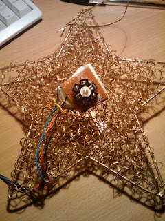


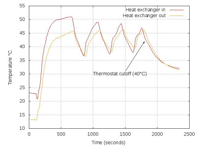
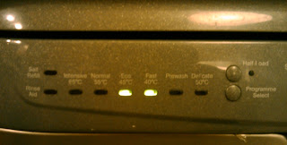
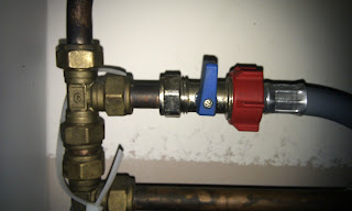



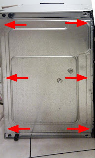
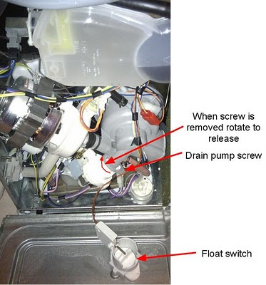
.jpg)


.png)

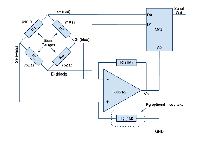.png)


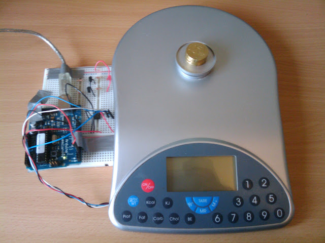

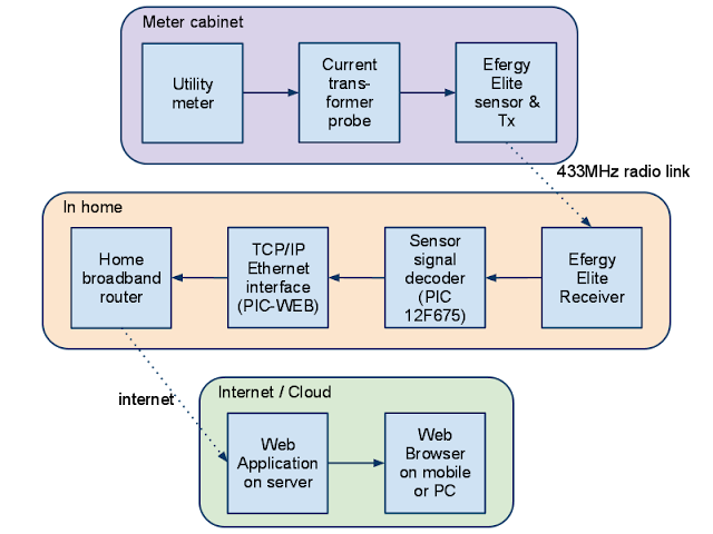.png)

