
This PMR set peaked my interest because of the external mic/headphone socket. I have the idea that perhaps these could be adapted to packet radio without any need to hack the hardware (I find these radios handy on occasion, so I'd prefer to also keep them functional as walkie-talkies).
There was a time when devices like this came with full schematics and a service manual. Sadly, nowadays, you have to figure out everything for yourself (unless someone else already has!).
Opening it doesn't take much effort. Two screws in the battery compartment and two screws covered by rubber bungs near the top.

The first thing I noticed was the 56 pin SOIC IC at the bottom of the board. This is a Matsushita AN29160AA transceiver chip which deals with most of the radio protocols details. Excerpt from the datasheet:
"AN29160AA is IC for Transceiver. One package involve four systems about IF, PLL, Regulator, and AF. Involving 1st IFamp, 2nd Mixer, 2nd IFamp, FM-Detector, 460MHz PLL, Regulator for RXRF/ TXRF/ VCO/ MCU, OPAMPs for filter and Speaker Amplifier."

To view the underside of the PCB, I found that I needed to remove a blob of glue which fixed the helical antenna to the case. I was then able to pry up the PCB enough to take photos. (To remove it fully I would have had to snip the speaker wires, and I wasn't bothered enough to do that).
On the underside there is the LCD in a metal case. I assume the MCU is also in that area. There are pads for the user interface rubber buttons. Next to the button pads is a test pad which could be used to solder a breakout wire. As I want to keep this functional, I'm not going to tear down any further... besides from experience, there isn't much that can be done with the MCUs on consumer devices. The test pad labeled "TX MOD" does make me curious though...
Best I can tell the CFWM 450HT is related to driving the peizzo speaker. Next to that a crystal can marked 21.7 (MHz?). The marking on the speaker is "JW 16Ω 0.5W".

The supplied headphones use a 3 pole 2.5mm audio plug and comprise a single ear piece and a pod with a mic/push-to-talk button.

Best I can tell so far: the plug tip is for the mic and push-to-talk switch and floats at about 2.4V, the middle ring of the plug is audio out for the ear piece. When no transmission is received it's at 0V, when a transmission is received it jumps to 2.2V with the audio signal superimposed. Last ring is ground.
Measuring the resistance of the mic line of the headset to ground I see that the resistance is 3k when the PTT switch is open and drops to 1.1k when the PTT switch is pressed/closed.

Update (1 Aug 2014): I got back to looking at interfacing this PMR to a microcontroller and took another look at the headset interface (the 3 pole 2.5mm jack socket at the top). I shall refer to the 3 lines as Tip, Middle and Sleeve. I still haven't figured it all out yet, but these are various measurements I've taken while the headset is connected.
- Tip-Sleeve resistance with PTT switch off: 2.9k
- Tip-Sleeve resistance with PTT switch pressed (on): 1k
- Middle-Sleeve resistance: 36 ohms (PTT switch has no effect)
- Tip-Middle resistance with PTT switch off: 2.8k
- Tip-Middle resistance with PTT switch pressed (on): 1.1k
- Voltage of Tip relative to Sleeve with PTT switch off: 2.45V
- Voltage of Tip relative to Sleeve with PTT switch on: 1.25V
- Voltage of Middle relative to Sleeve with nothing being received: 0V
- Voltage of Middle relative to Sleeve when receiving: 2.0V with audio out overlayed.
I also verified that shorting Tip to Sleeve via a 1.8k resistor will cause the unit to 'key up' and transmit (this was done with the headset disconnected). I found that the value of resistor is important. a 1k would cause the unit to only key up momentarily: the 1k resistor caused the Tip voltage to drop to about 0.9V which I guess is too low.
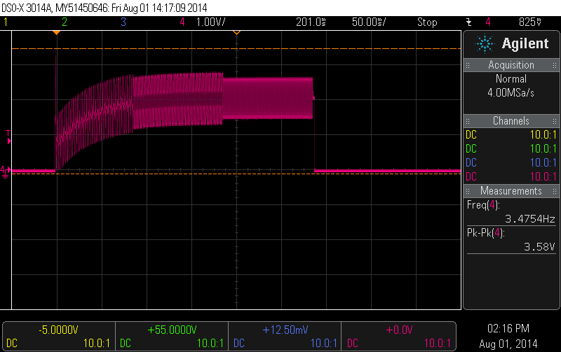
Here is scope trace from Middle (relative to Sleeve) when I key up and release. The waveform is the end-of-transmission bleep.
So in summary:
- Sleeve is ground.
- I can detect if there is an incoming signal by looking at the Middle DC offset. A value of about 2.5V indicates reception in progress. The AC part of the Middle is the received audio. Audio peak-to-peak voltage is about 1.5V at full volume.
- I can cause the unit to transmit by dropping the Tip voltage to about 1.25V (eg shorting through a 1.8k resistor)
- Still to do: interfacing a MCU DAC output to the audio in.
I'll update as I find out more.
5 comments:
The three pads component marked 21.7 is a 21.7 MHz 1st intermediate frequency (IF) filter. The one marked 450HT is the second IF filter at 450kHz. There's another 450kHz resonator for the quadrature Narrow Band FM (NBFM) detector in the other side of the board.
Hi. I have a pair of these radios and I am trying to get a PTT to work with them with no luck at all. The system I am using is an eBay special, military style headset with the oversized 4 way plug and a PTT button with a 2.5m plug for the radio end. The speaker works fine but the PTT either doesn't work at all or will activate the mic for a second and then it shuts off. Any tips would be appreciated, I am having a real hard time finding anything useful (read very ammature level) for this.
Hi, you can redrawing the headphones (3 pole 2.5mm) circuit?
Hello there i have those two walkie talkie and they are very good. But my problem is that the headsets are broken and don't work. I can't find them anywhere. Can you please help me?
Re replacement headset: If you search Ebay for "2.5mm headset" some possible replacements come up. But I'm not sure if they all have a standard pin out or not. If I can find an old Nokia heatset I'll give it a try. If it works with that, then you have something to go by.
Post a Comment